Categories
Categories
Brands
Brands
- Home
- CTDCP Disassembly and Reassembly
CTDCP Disassembly and Reassembly
ILLUSTRATED INSTRUCTION FOR DISASSEMBLY and REASSEMBLY OF THE CUTAWAY TRANSPARENT "DISMANTLEABLE" COMBINATION PADLOCK
IDENTIFICATION OF PARTS
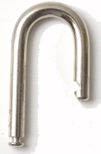 SHACKLE SHACKLE |
SHACKLE COLLAR |
WHEEL PACK (MOUNTED ON CLEAR PLASTIC DISK) |
LATCH MODULE |
| These step by step instructions pertain to our new cutaway lock - the CTDCP transparent combination padlock, which can be completely disassembled and reassembled. Please follow these guidelines carefully to avoid damaging the lock or ending up with an assembled lock that does not work. Also, please be aware that replacement parts are NOT available! Take special care to keep track of the parts as many of them are very small and easily lost. | 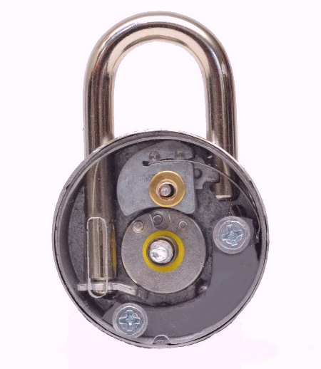 |
|
| STEP 1 - Remove both machine screws with a small Phillips screwdriver. | 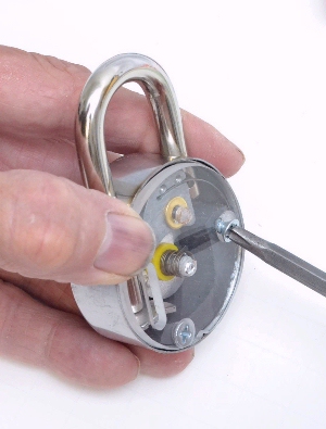 |
|
|
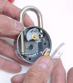
STEP 2 - Carefully remove the clear plastic disk which has the wheel pack attached to it. Set this part aside flat side down to avoid any damage to the wheel pack.
|
 |
|
| STEP 3 - Remove the brass spacer and lift out the shackle collar, taking note of how it is orientated to make later reassembly easier. | 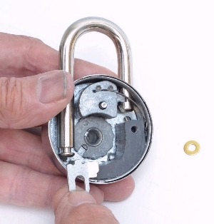 |
|
|
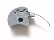
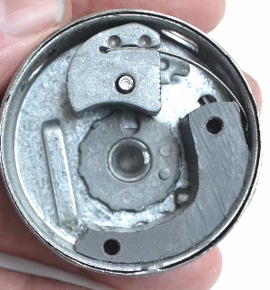
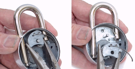
STEP 4 - Using needle nose pliers, or with your fingers if you have good finger strength, lift out the latch module. Take care to pull straight up and out. There will be some resistance due to the spring tension supplied by the curved spring.
|
 |
|
|
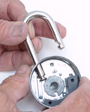
STEP 5 - Now you can pull out the shackle itself.
|
 |
|
|
STEP 6 - DISASSEMBLE THE WHEEL PACK
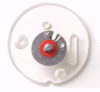
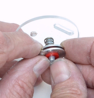
Begin by laying the wheel pack assembly (clear plastic disk and wheel pack attached) on a flat surface with its flat side down. Using both hands, place your thumbs on top of the mounting post as shown, and place your index fingers on both sides of the wheel stack. Push downward evenly with both thumbs as you apply upward pressure on the wheels with your index fingers. You are going to "pop off" the two wheels (you can do this one wheel at a time or pull off both wheels with one good pull). Resistance is felt because the red plastic spacers are indexed and they have to be forced up off the post.
|
 |
|
| Note that the post has a flat side and also a protruding lip that prevents the red spacer from slipping off. This is why you need to apply some force to remove these parts. The red spacers (there are 2 of them) are quite pliable and will withstand this procedure. When reassembling the wheel pack, be sure to align the tab on the red spacers with the flat on the post. | 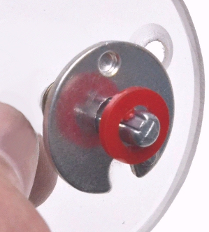 |
|
| It's good practice to set the parts of the wheel pack aside in the order that you removed them to make reassembly easier. Be sure to return the wheels in the same order (the wheel that was first to come off will be last to go back on). Also be sure the wheels are not inverted when you put them back on the post. The same side that was facing upward should face upward when returned to the post. If you happen to get one or both wheels on incorrectly, it could prevent the lock from working. | 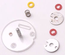 |
|
|
REASSEMBLE THE LOCK IN REVERSE ORDER. |
REASSEMBLY TIPS:
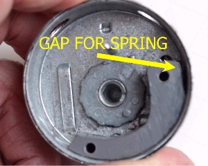
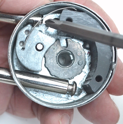
When inserting the latch module, make sure the tip of the curved stainless steel spring goes into the narrow gap provided for it.
Also, press the latch module down firmly onto its post. You'll probably hear it snap into place. |
|
|
When inserting the shackle, which is the next step after returning the latch module to the lock, it helps to keep the shackle straight as you push it down against the spring loaded latch. If you keep if aligned straight, it will probably snap right in, pushing the latch out of the way long enough for the shackle to seat. If you are not successful doing it this way, you may need to use a pointed tool to push the latch into the latch module while you push the shackle past it. |
 |
|
|
The next step in reassembly, after insertion of the shackle, is to install the tiny brass spacer/washer on the latch module. There is just enough of the mounting post poking up through it to hold the spacer in place until you attach the wheel pack. Now place the shackle collar around the groove in the shackle.
Now it's time to return the assembled wheel pack to the lock. If you haven't already reassembled the wheel pack, do it now. Remember, load each part onto the wheel pack post in the reverse order that they were removed. Here is a reminder of the proper order of reassembly:
First item onto the post: spring
|
|
|


 Loading... Please wait...
